1
/
of
1
woer
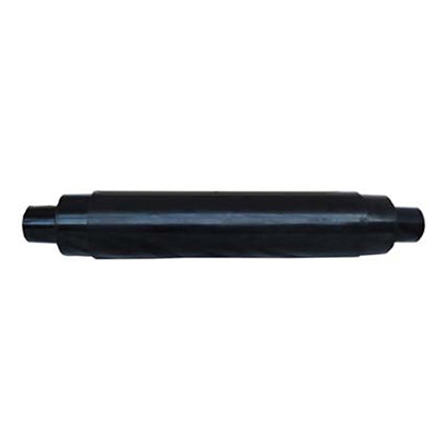
DC intermediate connector
DC intermediate connector
Regular price
0₫
Regular price
Sale price
0₫
Unit price
/
per
Couldn't load pickup availability
Application areas:
DC intermediate joints are mainly used in flexible high-voltage direct current (HVDC) transmission. They have gained widespread attention due to their flexible operating power range, operational independence, simplicity in power direction control, and superior transmission performance.
Product Description
-
The integral cable joint body is injection molded from high-quality EPDM rubber and is suitable for cross-linked polyethylene insulated cables with aluminum or copper conductors. It mainly consists of a joint body and an outer shell. The outer shell comprises a thick copper shell and a robust fiberglass shell, with high-voltage cable sealant filling the spaces between them. The product offers excellent mechanical protection, reliable electrical performance, and perfect sealing.
Product Parameters
- 1. VSC Load Cycling Test: The load cycle includes a heating cycle and a cooling cycle; 8 hours of heating followed by 16 hours of natural cooling constitutes one cycle. During the last two hours of the heating cycle, the conductor temperature is maintained at 70°C. The DC voltage UT during heating starts from the negative polarity. One reversal coincides with the load current stop time in the 24-hour load cycle. Each cycle is applied for 12 consecutive times.
- 2. VSC superimposed impulse voltage test (test conducted under thermal conditions):
- 2.1 DC superimposed operating impulse voltage test:
- Preheat and apply a positive polarity U0 voltage for at least 10 hours; under positive polarity U0, superimpose a positive polarity operating impulse voltage Up2,S for 10 consecutive times; under positive polarity U0, superimpose a positive polarity operating impulse voltage -Up2,O for 10 consecutive times.
- Preheat and apply a negative polarity U0 voltage for at least 10 hours; under negative polarity -U0, superimpose a positive polarity operating impulse voltage -Up2,S for 10 consecutive times; under negative polarity -U0, superimpose a positive polarity operating impulse voltage Up2,O for 10 consecutive times.
- 2.2 DC superimposed lightning impulse voltage test:
- Preheat and apply a positive polarity U0 voltage for at least 10 hours; then superimpose a negative polarity lightning impulse voltage -Up1 for 10 consecutive times.
- Preheat and apply a negative polarity -U0 voltage for at least 10 hours; then superimpose a positive polarity lightning impulse voltage Up1 for 10 consecutive times.
- 2.3 Subsequent DC voltage test
- Exposed to a negative polarity voltage -UT at room temperature for 2 hours.
| Rated voltage | ±150kV | ±320kV | |
| VSC load cycling test | UT | 277.5 | 592 |
| DC superposition operation impulse voltage test | U0 | 150 | 320 |
| Up2,S | 450 | 700 | |
| Up2,O | 290 | 700 | |
| DC superimposed lightning impulse voltage test | U0 | 160 | 320 |
| Up1 | 400 | 480 | |
| DC voltage test | UT | 277.5 | 592 |
| Rated voltage | kV | ±150 | ±320 | |
| Technical parameters | ||||
| Meets standards | 1. National Power Grid Conference Standard CIGRE 419 2. TICW7-2012 Test Specification for Extruded Insulated Power Cables for DC Transmission with Rated Voltage of 500kV and Below | |||
| Rated current | A | Not smaller than the connecting cable | ||
| short circuit current | Not smaller than the connecting cable | |||
| conductor connection | crimp type | |||
| Electric field control method | Geometric method | |||
| Stress cone material | EPDM | |||
| Filler glue | High-voltage cable sealant | |||
| Applicable cable cross-section | mm2 | 240-1600 | 400-2500 | |
| weight | Kg | 120 | 160 | |
| Applicable cable shielding/sheath | ||||
| Operating environment | ||||
| conductor rated temperature | During normal operation | ℃ | 90 | 90 |
| Short circuit | ℃ | 250 | 250 | |
| Suitable ambient temperature range | ℃ | -40-60 | -40-60 | |
| Laying method | ||||
| Permissible seismic intensity at the terminal | Spend | 8 | 8 | |
Product Selection
Share