woer
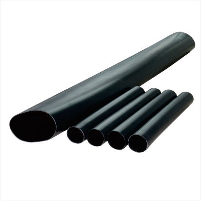
10kV heat shrink joint
10kV heat shrink joint
Couldn't load pickup availability
Application areas:
Intermediate treatment for 10kV cross-linked cables
Product Description
-
a . Many cable joint failures are caused by poor sealing. Our company uses a new process (three-layer sealing process) to make the cable safer and more reliable in operation. The so-called three-layer sealing refers to the outer sheath sealing, the inner sheath sealing, and the sealing at both ends of the inner insulation tube, for a total of three seals.
b . The insulation tube was lengthened, which solved the creepage problem.
c . The sheath is flexible and flame-retardant.
Product Parameters
|
Serial Number |
Test Item 1) |
Standard requirements |
|||
|
Indoor |
outdoor |
middle |
|||
|
1 |
Power frequency withstand voltage test |
AC 39kV , 5min or DC 35kV , 15min |
|||
|
Power frequency withstand voltage test under rain |
---- |
At 35kV , for 1 minute, the combined sample did not exhibit flashover or breakdown. |
------ |
||
|
2 |
Partial discharge test at room temperature |
No discharge was detected in the combined sample at 15kV. |
|||
|
3 |
High-temperature impulse voltage test, under θ t 2) |
95kV , 10 positive and 10 negative polarity impacts without flashover or breakdown |
|||
|
4 |
Constant pressure load cyclic test |
Cycled 60 times at temperature θt and 23kV (in air) |
Cycle 30 times (in air) and 30 times (in water ) at θt temperature and 23kV. |
||
|
5 |
Partial discharge (at θ t 2) 4) and ambient temperature t ) |
≤10pC at 15kV |
|||
|
6 |
Short-circuit thermal stability (shielded 5 ) |
Under the I SC shielding of the cable, two short circuits resulted in no visible damage; |
|||
|
7 |
Short-circuit thermal stability (conductor) |
When the conductor temperature is raised to θ SC , two short circuits occur without visible damage. |
|||
|
8 |
Short-circuit dynamic stability |
Under cable shielding condition I d , a single short circuit resulted in no visible damage. |
|||
|
9 |
Impulse voltage test |
95kV , 10 positive and 10 negative polarity impacts without flashover or breakdown |
|||
|
10 |
AC withstand voltage |
23kV , 15min |
|||
|
11 |
Fog test 7) |
11kV , 300H |
|||
|
12 |
Salt spray test 7) |
11kV , 1000H |
|||
|
1 ) Unless otherwise specified, the test shall be conducted at ambient temperature; 2 ) θt is the highest temperature of the conductor during normal operation plus (5-10)℃; 3 ) Each cycle lasts 8 hours, with a temperature stabilization time of at least 2 hours and a cooling time of at least 3 hours; 4 ) Take measurements at the end of the heating period; 5 ) This test is only applicable to terminals that can be directly or indirectly connected to the cable's metal shield via a bushing; 6 ) This requirement applies to single-core cable accessories with a peak current ip>80kA and three-core cable accessories with a peak current ip>63kA; 7 ) This requirement does not apply to the terminals of porcelain bushings and porcelain insulating bushings; for terminals with protective covers, testing should be conducted under three-phase conditions. |
|||||
Product Selection
|
voltage level |
Number of wire cores |
Cable cross-section /mm2 |
Product Code |
|
8.7/15(17.5)kV |
3,1 |
25-50 70-120 150-240 300-400 500-630 |
8.7/15kVRSJY-3/1(1/1) 8.7/15kVRSJY-3/2(1/2) 8.7/15kVRSJY-3/3(1/3) 8.7/15kVRSJY-3/4(1/4) 8.7/15kVRSJY-3/5(1/5) |
|
6/10(12)kV 6.35/11(12)kV |
3,1 |
25-50 70-120 150-240 300-400 500-630 |
6/10kVRSJY-3/1(1/1) 6/10kVRSJY-3/2(1/2) 6/10kVRSJY-3/3(1/3) 6/10kVRSJY-3/4(1/4) 6/10kVRSJY-3/5(1/5) |
Share