woer
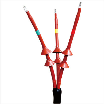
10kV heat shrink terminal
10kV heat shrink terminal
Couldn't load pickup availability
Application areas:
Termination treatment for 10kV cross-linked cables
Product Description
-
1. Cross-linked cable heat-shrinkable termination with dual ground wire technology. This means that the steel armor ground wire and the copper shield ground wire are separated, making the cable pre-testing more reasonable.
a . Measure the resistance of the steel armor ground wire to ground. If it is continuous, it indicates that the inner lining layer has been damaged. Measure the resistance of the copper shield ground wire to ground. If it is continuous, it indicates that both the inner and outer sheaths of the cable have been damaged.
c . For ease of construction, a triangular pad cone was developed.
d . The finger sleeve has a conical structure and will never crack.
Product Parameters
|
Serial Number |
Test Item 1) |
Standard requirements |
|||
|
Indoor |
outdoor |
middle |
|||
|
1 |
Power frequency withstand voltage test |
AC 39kV , 5min or DC 35kV , 15min |
|||
|
Power frequency withstand voltage test under rain |
---- |
At 35kV , for 1 minute, the combined sample did not exhibit flashover or breakdown. |
------ |
||
|
2 |
Partial discharge test at room temperature |
No detectable discharge was observed in the combined sample at 15kV. |
|||
|
3 |
High-temperature impulse voltage test, under θ t 2) |
95kV , 10 positive and 10 negative polarity impacts without flashover or breakdown |
|||
|
4 |
Constant pressure load cyclic test |
Cycled 60 times at temperature θt and 23kV (in air) |
Cycle 30 times (in air) and 30 times (in water ) at θt temperature and 23kV. |
||
|
5 |
Partial discharge (at θ t 2 ) 4) and ambient temperature t ) |
≤10pC at 15kV |
|||
|
6 |
Short-circuit thermal stability (shielded 5 ) |
Under the I SC shielding of the cable, two short circuits resulted in no visible damage; |
|||
|
7 |
Short-circuit thermal stability (conductor) |
When the conductor temperature is raised to θ SC , two short circuits occur without visible damage. |
|||
|
8 |
Short-circuit dynamic stability |
Under cable shielding condition I d , a single short circuit resulted in no visible damage. |
|||
|
9 |
Impulse voltage test |
95kV , 10 positive and 10 negative polarity impacts without flashover or breakdown |
|||
|
10 |
AC withstand voltage |
23kV , 15min |
|||
|
11 |
Fog test 7) |
11kV , 300H |
|||
|
12 |
Salt spray test 7) |
11kV , 1000H |
|||
|
1 ) Unless otherwise specified, the test shall be conducted at ambient temperature; 2 ) θt is the highest temperature of the conductor during normal operation plus (5-10)℃; 3 ) Each cycle lasts 8 hours, with a temperature stabilization time of at least 2 hours and a cooling time of at least 3 hours; 4 ) Take measurements at the end of the heating period; 5 ) This test is only applicable to terminals that can be directly or indirectly connected to the cable's metal shield via a bushing; 6 ) This requirement applies to single-core cable accessories with a peak current ip>80kA and three-core cable accessories with a peak current ip>63kA; 7 ) This requirement does not apply to the terminals of porcelain bushings and porcelain insulating bushings; for terminals with protective covers, testing should be conducted under three-phase conditions. |
|||||
Product Selection
|
voltage level |
Number of wire cores |
Cable cross-section /mm2 |
Indoor terminal product code |
Outdoor terminal product code |
|
8.7/15(17.5)kV |
3,1 |
25-50 70-120 150-240 300-400 500-630 |
8.7/15kVRSNY-3/1(1/1) 8.7/15kVRSNY-3/2(1/2) 8.7/15kVRSNY-3/3(1/3) 8.7/15kVRSNY-3/4(1/4) 8.7/15kVRSNY-3/5(1/5) |
8.7/15kVRSWY-3/1(1/1) 8.7/15kVRSWY-3/2(1/2) 8.7/15kVRSWY-3/3(1/3) 8.7/15kVRSWY-3/4(1/4) 8.7/15kVRSWY-3/5(1/5) |
|
6/10(12)kV 6.35/11(12)kV |
3,1 |
25-50 70-120 150-240 300-400 500-630 |
6/10kVRSNY-3/1(1/1) 6/10kVRSNY-3/2(1/2) 6/10kVRSNY-3/3(1/3) 6/10kVRSNY-3/4(1/4) 6/10kVRSNY-3/5(1/5) |
6/10kVRSWY-3/1(1/1) 6/10kVRSWY-3/2(1/2) 6/10kVRSWY-3/3(1/3) 6/10kVRSWY-3/4(1/4) 6/10kVRSNY-3/5(1/5) |
Share