woer
Waterproof intermediate joint
Waterproof intermediate joint
Couldn't load pickup availability
Application areas:
Suitable for most circuits, including those with high waterproofing requirements, areas prone to failure, and areas susceptible to water immersion.
Product Description
-
The waterproof intermediate joint features water-blocking structural layers on its main body, inner sheath, and outer sheath to achieve overall radial water blocking. High-viscosity water-blocking materials are applied at different interface joints to enhance axial waterproofing. Internally, the waterproof intermediate joint utilizes highly efficient water-blocking materials and a core-based water-blocking process. These materials exhibit superior shape resistance, creep resistance, and adhesion. Even with water ingress into the core, the internal waterproofing material adapts to the water volume to maintain waterproofing performance, and its water-blocking properties remain unchanged over time and operating temperature.
The internal waterproof structure is composed of conductive materials, stress control materials, and insulating materials. The conductive material has high conductivity, good adhesion to metals and PE, is non-absorbent, has good shape retention, and does not harden. Its function is to restore the semiconductive layer inside the conductor, achieving long-term water resistance at conductor shielding breaks and preventing water leakage from the cable core. The stress control material has stable performance and good adhesion to metals and PE. Its function is to distribute the electric field uniformly and control the surface electrical stress of the inner semiconductive layer. The insulating material has a dielectric constant similar to that of the cable insulation, good adhesion to PE and SR, and its function is to enhance the insulation performance at intermediate joints, weaken interface effects, and restore water resistance inside the joint.
Waterproof intermediate joints feature bidirectional water resistance both inside and outside the joint location, superior electrical performance, and convenient installation.
Features:
- Waterproof materials
- 1. Conductive material: High electrical conductivity, good adhesion to metals and PE, non-absorbent, good shape retention, creep resistant, water-blocking, and with stable electrical properties.
- 2. Stress control material: Stable performance, good adhesion to metals and PE.
- 3. Insulating material: The dielectric constant is similar to that of the insulation material, with high elongation at break and good adhesion to PE and SR.
- Waterproof structure
- 1. Increase the pressure at the insulation interface and improve the electric field distribution.
- 2. Enhance the interfacial pressure and sealing performance at the insulation shield break point, and improve the external water resistance effect.
- 3. Modify the structure and process at the conductor shield break point to achieve axial and radial water blocking inside the joint.
- Waterproofing process
- 1. Reduce requirements for the installation environment and broaden the product's adaptability.
- 2. Reduce reliance on installation techniques and improve product qualification rate.
Product Parameters
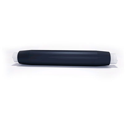
Waterproof intermediate joint appearance and main body cross section drawing

8.7/15kV Waterproof Intermediate Joint Performance (Type Test)
Serial Number Test Project Standard requirements 1 Test Procedure 1.1 AC withstand voltage test (39kV, 5min) Non-penetration 1.2 AC withstand voltage test (55kV, 5min) Non-penetration 1.3 Partial discharge test (15KV) ≤2pC 1.4 Impulse voltage test (95℃~100℃, 95kV, 10 times each for positive and negative polarities) Non-penetration 1.5 Impulse voltage test (95℃~100℃, 115kV, 10 times each for positive and negative polarities) Non-penetration 1.6 Constant pressure load cycling test in air (22KV. Heating cycle for at least 8 hours, conductor stabilized at 95℃~100℃ for at least 2 hours, natural cooling for at least 3 hours, for a total of 30 thermal cycles) Non-penetration 1.7 Underwater constant pressure load cyclic test (22KV. Heating cycle for at least 8 hours, conductor stabilized at 95℃~100℃ for at least 2 hours, natural cooling for at least 3 hours, for a total of 60 thermal cycles. Water is injected into the conductor from the cable end, and the water pressure of the intermediate joint conductor is maintained at 1m by adjusting the height of the end. At the same time, the intermediate joint is completely submerged in water, with the water level 1m above the intermediate joint.) Non-penetration 1.8 Partial discharge test 1.8.1 Partial discharge (15kV, 95℃~100℃) ≤2pC 1.8.2 Partial discharge (15kV, ambient temperature) ≤2pC 1.9 Impulse voltage test (95KV, 10 times each for positive and negative polarities). Non-penetration 1.10 Impulse voltage test (95℃~100℃, 115kV, 10 times each for positive and negative polarities). Non-penetration 1.11 AC withstand voltage test (22kV, 15min) Non-penetration 1.12 Inspection (testing) No abnormalities found in the sample 2 Test Procedure 2.1 AC withstand voltage test (39kV, 5min) Non-penetration 2.2 Short-circuit thermal stability test (raised to θSC of the cable conductor, 2s, short-circuited twice). No visible damage 2.3 Short-circuit dynamic stability test (at Id, not less than 10ms, once). No visible damage 2.4 Impulse voltage test (95kV, 10 times each for positive and negative polarities) Non-penetration 2.5 AC withstand voltage test (22kV, 15min) Non-penetration 2.6 Inspection (testing) No abnormalities found in the sample Performance of 26/35kV waterproof intermediate joint (type test)
Serial Number Test Project Standard requirements 1 Test Procedure 1.1 AC withstand voltage test (117kV, 5min) Non-penetration 1.2 Partial discharge test (45KV) ≤10pC 1.3 Impulse voltage test (95℃~100℃, 200kV, 10 times each for positive and negative polarities) Non-penetration 1.4 Constant pressure load cyclic test in air (65KV. Water is injected into the conductor from the cable end, and the water pressure at the intermediate joint conductor is maintained at 1m by adjusting the height of the end. Heating cycle for at least 8 hours, conductor stabilized at 95℃~100℃ for at least 2 hours, natural cooling for at least 3 hours, for a total of 30 thermal cycles) Non-penetration 1.5 Underwater constant pressure load cyclic test (65KV. Heating cycle for at least 8 hours, conductor stabilized at 95℃~100℃ for at least 2 hours, natural cooling for at least 3 hours, for a total of 30 thermal cycles. Water is injected into the conductor from the cable end, and the water pressure of the intermediate joint conductor is maintained at 1m by adjusting the height of the end. At the same time, the intermediate joint is completely submerged in water, with the water level 1m above the intermediate joint.) Non-penetration 1.6 Partial discharge test 1.6.1 Partial discharge (45kV, 95℃~100℃) ≤2pC 1.6.2 Partial discharge (45kV, ambient temperature) ≤2pC 1.7 Impulse voltage test (200KV, 10 times each for positive and negative polarities). Non-penetration 1.8 AC withstand voltage test (22kV, 15min) Non-penetration 1.9 Inspection (testing) No abnormalities found in the sample 2 Test Procedure 2.1 AC withstand voltage test (117kV, 5min) Non-penetration 2.2 Short-circuit thermal stability test (raised to θSC of the cable conductor, 2s, short-circuited twice). No visible damage 2.3 Short-circuit dynamic stability test (at Id, not less than 10ms, once). No visible damage 2.4 Impulse voltage test (200kV, 10 times each for positive and negative polarities). Non-penetration 2.5 AC withstand voltage test (65kV, 15min) Non-penetration 2.6 Inspection (testing) No abnormalities found in the sample We are committed to continuous product improvement, therefore we reserve the right to change designs, sizes, and data without prior notice.
Product Selection
The product's model number, rated voltage, application, and applicable cable cross-sectional area are composed of codes, as shown in the figure:
- 1. Selection of 8.7/15kV (12/20kV) waterproof intermediate joint

- 2. Selection of 18/20KV waterproof intermediate joint
-
The product's model number, rated voltage, application, and applicable cable cross-sectional area are composed of codes, as shown in the figure.

- 3. Selection of 26/35kV waterproof intermediate joint
-
The product's model number, rated voltage, application, and applicable cable cross-sectional area are composed of codes, as shown in the figure: