1
/
of
1
woer
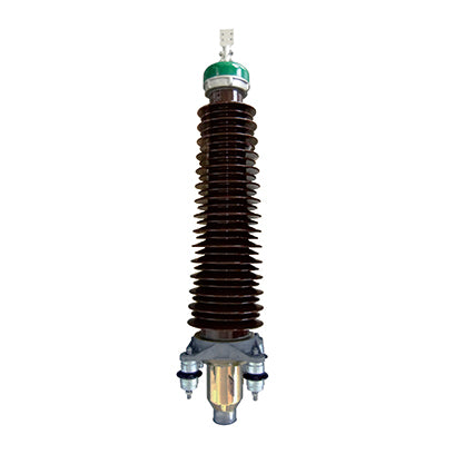
DC porcelain-insulated outdoor terminal
DC porcelain-insulated outdoor terminal
Regular price
0₫
Regular price
Sale price
0₫
Unit price
/
per
Couldn't load pickup availability
Application areas:
It is mainly used in the field of flexible high-voltage direct current transmission. It has gained widespread attention due to its flexible and variable operating power range, independent operation, simple power direction control and superior transmission performance.
Product Description
-
1. The external insulation of this terminal uses porcelain bushing insulation tubing, suitable for operation in coastal and highly polluted areas. The insulation level, current carrying capacity, and operating temperature of this terminal fully meet the requirements of the cables it is used with. 2. The terminal stress cone is made of imported EPDM rubber through high-pressure injection molding, secured by a spring cone support. A stress cone cover structure isolates the stress cone from the insulating filler, overcoming the problems of elastic relaxation due to material aging and poor contact between the stress cone and the outer semiconducting layer of the cable, ensuring long-term safe and stable operation of the terminal. 3. The porcelain bushing is made of high-strength high-voltage porcelain, possessing excellent weather resistance, anti-tracking, anti-electrode corrosion ability, and water-repellent properties. 4. The terminal adopts a multi-layer sealing structure to prevent water seepage and oil leakage during operation. 5. The terminal bushing uses a large and small umbrella skirt structure, providing excellent anti-pollution flashover characteristics.
Product Parameters
- 1. VSC Load Cycling Test: The load cycle includes a heating cycle and a cooling cycle; 8 hours of heating followed by 16 hours of natural cooling constitutes one cycle. During the last two hours of the heating cycle, the conductor temperature is maintained at 70°C. The DC voltage UT during heating starts from the negative polarity. One reversal coincides with the load current stop time in the 24-hour load cycle. Each cycle is applied for 12 consecutive times.
- 2. VSC superimposed impulse voltage test (test conducted under thermal conditions):
- 2.1 DC superimposed operating impulse voltage test:
- Preheat and apply a positive polarity U0 voltage for at least 10 hours; under positive polarity U0, superimpose a positive polarity operating impulse voltage Up2,S for 10 consecutive times; under positive polarity U0, superimpose a positive polarity operating impulse voltage -Up2,O for 10 consecutive times.
- Preheat and apply a negative polarity U0 voltage for at least 10 hours; under negative polarity -U0, superimpose a positive polarity operating impulse voltage -Up2,S for 10 consecutive times; under negative polarity -U0, superimpose a positive polarity operating impulse voltage Up2,O for 10 consecutive times.
- 2.2 DC superimposed lightning impulse voltage test:
- Preheat and apply a positive polarity U0 voltage for at least 10 hours; then superimpose a negative polarity lightning impulse voltage -Up1 for 10 consecutive times.
- Preheat and apply a negative polarity -U0 voltage for at least 10 hours; then superimpose a positive polarity lightning impulse voltage Up1 for 10 consecutive times.
- 2.3 Subsequent DC voltage test
- Exposed to a negative polarity voltage -UT at room temperature for 2 hours.
| Rated voltage | ±150kV | ±320kV | |
| VSC load cycling test | UT | 277.5 | 592 |
| DC superposition operation impulse voltage test | U0 | 150 | 320 |
| Up2,S | 450 | 700 | |
| Up2,O | 290 | 700 | |
| DC superimposed lightning impulse voltage test | U0 | 160 | 320 |
| Up1 | 400 | 480 | |
| DC voltage test | UT | 277.5 | 592 |
| Rated voltage | kV | ±150 | ±320 | |
| Technical parameters | ||||
| Meets standards | 1. National Power Grid Conference Standard CIGRE 419 2. TICW7-2012 Test Specification for Extruded Insulated Power Cables for DC Transmission with Rated Voltage of 500kV and Below | |||
| Rated current | A | Not smaller than the connecting cable | ||
| short circuit current | Not smaller than the connecting cable | |||
| conductor connection | crimp type | |||
| Electric field control method | Geometric method | |||
| Insulating filler | silicone oil | |||
| creepage distance | mm | >4495 | >7812 | |
| Applicable cable cross-section | mm2 | 240-1600 | 400-2500 | |
| weight | Kg | 240 | 1000 | |
| Applicable cable shielding/sheath | ||||
| Operating environment | ||||
| conductor rated temperature | During normal operation | ℃ | 90 | 90 |
| Short circuit | ℃ | 250 | 250 | |
| Suitable ambient temperature range | ℃ | -40-60 | -40-60 | |
| Altitude of the area of use | m | 3000 | 3000 | |
| Permissible seismic intensity at the terminal | Spend | 8 | 8 | |
| The terminal allows for horizontal tensile force on the connecting wires. | kN | 2 | 2 | |
| Bending strength | kN∙m | 8 | 20 | |
| Maximum internal pressure | MPa | 2 | 2 | |
Product Selection
Share